Kornylak Corporation
400 Heaton St.
Hamilton, OH 45011
PH: 513.863.1277
TF: 800.837.5676
F: 513.863.7644
Cartonflo® Storage Rack Design
Cartonflo
Rack Design
• Cartonflo
• Additional
• Brochures
<< Back
• Specifications
• Summary
• Information Request
• Product Literature
• Home
Quick Find:
Conveyors : Armorbelt | Cartonflo | Macrobelt | Monoflo | Palletflo | Rollerflo | TKV | TS Live Roller | Trakwheel | Vertiflo | Zipflo
Design Guidelines For Your Cartonflo® Storage Racks
 |
||||||||||||||||||||||||||||||||||||||
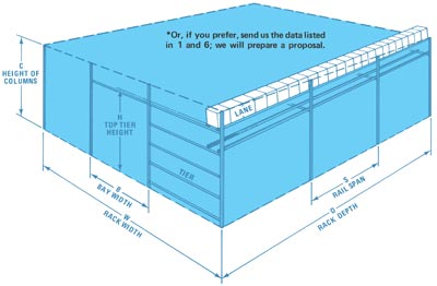
| Legend B Bay width | C Column height | D Rack Depth | H Height of top tier L Number of lanes per tier | N Number of tiers | S Rail span | T Teir weight Y Total number of lanes | W Rack width |
||||||||||||||||||||||||||||||||||||||
| 1 | Compute Data for Each Individual Product d Carton depth (inches) h Carton height (inches) Q Total stocking quantity U Weight per foot (pounds per foot) = wt x 12/d w Carton Width (inches) wt Gross carton weight (pounds) X Total stocking depth (feet) = Q x d/12 |
|||||||||||||||||||||||||||||||||||||
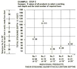
| 2 | Make a Comparison Graph of All X Values These compared values may show that approximately 20% of the products make up 80% of the flow. They can be used to establish the working rack depth D (feet) and the total number of required lanes Y. As shown in the following example, for a selected rack depth of 30 feet, Y=2 of product no. 1, 4 of product no. 2, 1 product no. 3, etc. Note: Rack depths of 10 to 40 feet are most popular. |
 |
||||||||||||||||||||||||||||||||||||
| 3 | Normally Top Tier Height H (inches) at Front of Rack is 72". (Bottom of carton at picking face) Other heights may apply to suit space conditions or special picking arrangements. |
|||||||||||||||||||||||||||||||||||||
| 4 | Number of Tiers N=[H/[h of tallest carton on tier + 6"]] |
|||||||||||||||||||||||||||||||||||||
| 5 | Number of Lanes per Tier L=Y/N The information derived above should now be checked against actual building condition as follows: (a floor plan is recommended) |
|||||||||||||||||||||||||||||||||||||
| 6 | Record Data on Floor Space, Obstructions, Product Flow, Loading and Unloading Areas
|
|||||||||||||||||||||||||||||||||||||
| 7 | Check the Building Specs to Verify that Desired Working Rack Depth D from Step 2 is Valid, Considering Loading and Unloading Areas as Well as Floor Lines as Mentioned in Step 6. If D is not compatible, go back to Step 2 and refigure to suit. |
|||||||||||||||||||||||||||||||||||||
| 8 | Rack Width W is equal to the width of all the cartons on one tier plus 2" clearance per carton. ie., W= [average carton width + 2"] X L CONDITION: The calculated W must be less than its space limitation in the building (between columns or obstructions, etc.) If not, the system must be broken down into smaller racks. |
|||||||||||||||||||||||||||||||||||||
| 9 | Height of the Rack Column C is equal to the top tier height plus inch per foot of rack depth D (a conservative allowance for the pitch of all the rails). ie., C=H (inches) + [D x 1] (inches) CONDITION: C + height of tallest carton on top tier + 2” clearance must be less than the ceiling imitations in that area of the rack. If not, a compromise between the track depth, top tier height and number of tiers must be refigured from Step 2 |
|||||||||||||||||||||||||||||||||||||
| 10 | Rail Span S Using maximum unit carton weight U NOTE: The selected value must be divisible into the working rack depth D (Step 2). |
|
||||||||||||||||||||||||||||||||||||
| 11 | Tier Weight T represents the total load acting on the rail cross-beam and is a function of maximum carton weight, rail span and the number of lanes in the bay. ie., T=U max. x S x [desired number of lanes in bay] |
|||||||||||||||||||||||||||||||||||||
| 12 | Bay width B NOTE: Bay width must be divisible into rack width W (Step 8). |
|
||||||||||||||||||||||||||||||||||||
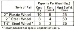
| 13 | Rail Style & Wheel Spacing Standard Cartonflo rails are available with wheels mounted on one or both sides, spaced at 2", 3", 4", 5", and 6" centers. The proper wheel spacing is one which is less than 1/3 of the length of the shortest box to be stored. In special cases, where the bottom surface of the item is hard and flat, the spacing can be increased to a dimension less than 1/2 of the item length. When determining wheel spacing, check the wheel loading table below to be sure that the load per wheel does not exceed the recommended maximum wheel load. |
 |
||||||||||||||||||||||||||||||||||||
Suggestions to improve our website: Survey
Top | BackConveyors | Wheels | Insulation | Vehicles | Products | Literature | Sitemap
Robots | Services | Corporate Facts | Contact Us | FAQ | Info. Request | News
Resources | Links | Directories Links | Organizations Links | Publications Links
Copyright © 1998-2008 Kornylak Corporation